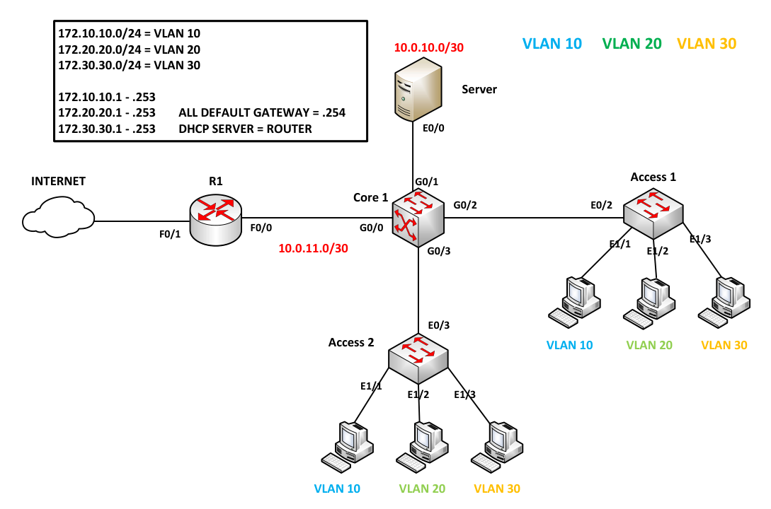
Layer 3 Switch Inter-VLAN with DHCP and NAT
Configuring Core1 (L3 Switch)
If you prefer not to configure manually, I've saved the startup config on my GitHub page. Click the GitHub link at the top right.
On Core1, set the hostname to 'Core1', create the necessary VLANs 10, 20, 30, and assign G1/1, G1/2, and G1/3 to their respective VLANs based on the diagram.
Switch>enable
Switch#config terminal
Enter configuration commands, one per line.  End with CNTL/Z.
Switch(config)#hostname Core1
Core1(config)#
Core1(config)#vlan 10
Core1(config-vlan)#vlan 20
Core1(config-vlan)#vlan 30
Core1(config-vlan)#
Now that the VLANs are created, type the command 'show vlan brief' to check the necessary VLANs
Core1(config-vlan)#
Core1(config-vlan)#end
Core1#show vlan brief
VLAN Name                             Status    Ports
---- -------------------------------- --------- -------------------------------
1    default                          active    Gi0/3, Gi1/0, Gi1/1, Gi1/2
                                                Gi1/3, Gi2/0, Gi2/1, Gi2/2
                                                Gi2/3, Gi3/0, Gi3/1, Gi3/2
                                                Gi3/3
10   VLAN0010                         active
20   VLAN0020                         active
30   VLAN0030                         active
1002 fddi-default                     act/unsup
1003 token-ring-default               act/unsup
1004 fddinet-default                  act/unsup
1005 trnet-default                    act/unsup

Core1#
Now, create SVIs (Switched Virtual Interfaces); these will serve as the default gateways for each VLAN. Additionally, add the IP address of the DHCP Server to inform Core1 on how to redirect DHCP broadcast traffic. Use the command 'ip helper-address {server}' and use show ip interface brief to verify the config.To enable routing between VLANs, execute the command 'ip routing'.
Core1 Config
    Core1#conf t
    Enter configuration commands, one per line.  End with CNTL/Z.
    Core1(config)#
    Core1(config)#interface vlan10
    Core1(config-if)#ip address 172.10.10.254 255.255.255.0
    Core1(config-if)#ip helper-address
    Core1(config-if)#ip helper-address 10.0.10.1
    Core1(config-if)#no shutdown
    Core1(config-if)#
    Core1(config-if)#int vlan 20
    Core1(config-if)#ip address 172.20.20.254 255.255.255.0
    Core1(config-if)#ip helper-address 10.0.10.1
    Core1(config-if)#no shutdown
    Core1(config-if)#
    Core1(config-if)#int vlan 30
    Core1(config-if)#ip address 172.30.30.254 255.255.255.0
    Core1(config-if)#ip helper-address 10.0.10.1
    Core1(config-if)#no shutdown
    Core1(config-if)#
    Core1(config-if)#end
    Core1#
    Core1#configure terminal
    Enter configuration commands, one per line.  End with CNTL/Z.
    Core1(config)#
    Core1(config)#ip routing
    Core1(config)#
Core1 Verification
    Core1#show ip interface brief
    Interface              IP-Address      OK? Method Status                Protocol
    GigabitEthernet0/2     unassigned      YES unset  up                    up
    GigabitEthernet0/3     unassigned      YES unset  down                  down
    GigabitEthernet0/0     unassigned      YES unset  down                  down
    GigabitEthernet0/1     unassigned      YES unset  down                  down
    GigabitEthernet1/0     unassigned      YES unset  down                  down
    GigabitEthernet1/1     unassigned      YES unset  up                    up
    GigabitEthernet1/2     unassigned      YES unset  up                    up
    GigabitEthernet1/3     unassigned      YES unset  up                    up
    GigabitEthernet2/0     unassigned      YES unset  down                  down
    GigabitEthernet2/1     unassigned      YES unset  down                  down
    GigabitEthernet2/2     unassigned      YES unset  down                  down
    GigabitEthernet2/3     unassigned      YES unset  down                  down
    GigabitEthernet3/0     unassigned      YES unset  down                  down
    GigabitEthernet3/1     unassigned      YES unset  down                  down
    GigabitEthernet3/2     unassigned      YES unset  down                  down
    GigabitEthernet3/3     unassigned      YES unset  down                  down
    Vlan10                 172.10.10.254   YES NVRAM  up                    up
    Vlan20                 172.20.20.254   YES NVRAM  up                    up
    Vlan30                 172.30.30.254   YES NVRAM  up                    up
Now, we create routed ports connected to the server and router. The network between the server and Core1 is 10.0.10.0/30, and between R1 and Core1 is 10.0.11.0/30.
Core1(config)#
Core1(config)#interface g0/0
Core1(config-if)#no switchport
Core1(config-if)#
Core1(config-if)#ip address 10.0.11.2 255.255.255.252
Core1(config-if)#no shutdown
Core1(config-if)#
Core1(config-if)#interface g0/1
Core1(config-if)#no switchport
Core1(config-if)#ip address 10.0.10.2 255.255.255.252
Core1(config-if)#no shutdown
Core1(config-if)#end
Core1#
Core1#
Core1#show ip interface brief | exc unass
Interface              IP-Address      OK? Method Status                Protocol
GigabitEthernet0/0     10.0.11.2       YES NVRAM  up                    up
GigabitEthernet0/1     10.0.10.2       YES NVRAM  up                    up
Vlan10                 172.10.10.254   YES NVRAM  up                    up
Vlan20                 172.20.20.254   YES NVRAM  up                    up
Vlan30                 172.30.30.254   YES NVRAM  up                    up

Core1#
Now, configure a trunk to the neighboring switch, Access1 and Acess2, allowing only the necessary VLANs and disabling DTP.
If the switch supports both ISL and 802.1Q, use the command switchport trunk encapsulation dot1q.
Core1#conf t
Enter configuration commands, one per line.  End with CNTL/Z.
Core1(config)#
Core1(config)#int range g0/2 - 3
Core1(config-if-range)#
Core1(config-if-range)#switchport trunk encapsulation dot1q
Core1(config-if-range)#switchport mode trunk
Core1(config-if-range)#
Core1(config-if-range)#switchport trunk allowed vlan 10,20,30
Core1(config-if-range)#switchport nonegotiate
Core1(config-if-range)#end
Core1#
Core1#
Core1#show interface trunk

Port        Mode             Encapsulation  Status        Native vlan
Gi0/2       on               802.1q         trunking      1
Gi0/3       on               802.1q         trunking      1

Port        Vlans allowed on trunk
Gi0/2       10,20,30
Gi0/3       10,20,30

Port        Vlans allowed and active in management domain
Gi0/2       10,20,30
Gi0/3       10,20,30

Port        Vlans in spanning tree forwarding state and not pruned
Gi0/2       10,20,30
Gi0/3       10,20,30
Core1#
Configuring Access1 (L2 Switch)
Now, add the interfaces to their necessary VLANs on Access1 and configure a trunk to the neighboring switch, allowing only the necessary VLANs and disabling DTP.
Access1 Configuration
    Switch>enable
    Switch#config terminal
    Enter configuration commands, one per line.  End with CNTL/Z.
    Switch(config)#hostname Access1
    Access1(config)#
    Access1(config)#vlan 10
    Access1(config-vlan)#vlan 20
    Access1(config-vlan)#vlan 30
    Access1(config-vlan)#
    Access1#
    Access1#conf t
    Access1(config)#
    Access1(config)#interface e1/1
    Access1(config-if)#switchport access vlan 10
    Access1(config-if)#
    Access1(config-if)#int e1/2
    Access1(config-if)#switchport access vlan 20
    Access1(config-if)#
    Access1(config-if)#int e1/3
    Access1(config-if)#switchport access vlan 30
    Access1(config-if)#end
    Access1#
Access1 Configuration Part 2
    Access1#conf t
    Enter configuration commands, one per line.  End with CNTL/Z.
    Access1(config)#
    Access1(config)#int e0/3
    Access1(config-if)#
    Access1(config-if)#switchport trunk encapsulation dot1q
    Access1(config-if)#switchport mode trunk
    Access1(config-if)#
    Access1(config-if)#switchport trunk allowed vlan 10,20,30
    Access1(config-if)#switchport nonegotiate
    Access1(config-if)#end
    Access1#
Configuring Access2 (L2 Switch)
Now, add the interfaces to their necessary VLANs on Access2 and configure a trunk to the neighboring switch, allowing only the necessary VLANs and disabling DTP.
Access2 Configuration
    Switch>enable
    Switch#config terminal
    Enter configuration commands, one per line.  End with CNTL/Z.
    Switch(config)#hostname Access2
    Access2(config)#
    Access2(config)#vlan 10
    Access2(config-vlan)#vlan 20
    Access2(config-vlan)#vlan 30
    Access2(config-vlan)#
    Access2#
    Access2#conf t
    Access2(config)#
    Access2(config)#interface e1/1
    Access2(config-if)#switchport access vlan 10
    Access2(config-if)#
    Access2(config-if)#int e1/2
    Access2(config-if)#switchport access vlan 20
    Access2(config-if)#
    Access2(config-if)#int e1/3
    Access2(config-if)#switchport access vlan 30
    Access2(config-if)#end
    Access2#
Access2 Configuration Part 2
    Access2#conf t
    Enter configuration commands, one per line.  End with CNTL/Z.
    Access2(config)#
    Access2(config)#int e0/2
    Access2(config-if)#
    Access2(config-if)#switchport trunk encapsulation dot1q
    Access2(config-if)#switchport mode trunk
    Access2(config-if)#
    Access2(config-if)#switchport trunk allowed vlan 10,20,30
    Access2(config-if)#switchport nonegotiate
    Access2(config-if)#end
    Access2#
Configuring Router as DHCP Server
As for the server, instead of using a Windows server, we will use a router to perform DHCP.
Configure Server
    DHCP#
    DHCP#conf t
    DHCP(config)#
    DHCP(config)#interface ethernet 0/0
    DHCP(config-if)#ip address 10.0.10.1 255.255.255.252
    DHCP(config-if)#no shutdown
    DHCP(config-if)#
Verification Server
    DHCP#show ip int brief | excl unas
    Interface                  IP-Address      OK? Method Status                Protocol
    Ethernet0/0                10.0.10.1       YES manual up                    up

    DHCP#
When configuring the DHCP server, indicate the excluded addresses so that the server knows which addresses are excluded from leases.
DHCP#conf t
Enter configuration commands, one per line.  End with CNTL/Z.
DHCP(config)#ip dhcp excluded-address 172.10.10.254
DHCP(config)#ip dhcp excluded-address 172.20.20.254
DHCP(config)#ip dhcp excluded-address 172.30.30.254
DHCP(config)#
To ensure that PCs in different VLANs receive an IP address, create a DHCP pool that includes the range of addresses and specifies the default gateway.
DHCP Configuration
    DHCP(config)#
    DHCP(config)#ip dhcp pool VLAN10
    DHCP(dhcp-config)#network 172.10.10.0 255.255.255.0
    DHCP(dhcp-config)#default-router 172.10.10.254
    DHCP(dhcp-config)#
    DHCP(dhcp-config)#ip dhcp pool VLAN20
    DHCP(dhcp-config)#network 172.20.20.0 255.255.255.0
    DHCP(dhcp-config)#default-router 172.20.20.254
    DHCP(dhcp-config)#
    DHCP(dhcp-config)#ip dhcp pool VLAN30
    DHCP(dhcp-config)#network 172.30.30.0 255.255.255.0
    DHCP(dhcp-config)#default-router 172.30.30.254
    DHCP(dhcp-config)#end
    DHCP#
Verification
    DHCP#show ip dhcp pool

    Pool VLAN10 :
     Utilization mark (high/low)    : 100 / 0
     Subnet size (first/next)       : 0 / 0
     Total addresses                : 254
     Leased addresses               : 0
     Pending event                  : none
     1 subnet is currently in the pool :
     Current index        IP address range                    Leased addresses
     172.10.10.1          172.10.10.1      - 172.10.10.254     0

    Pool VLAN20 :
     Utilization mark (high/low)    : 100 / 0
     Subnet size (first/next)       : 0 / 0
     Total addresses                : 254
     Leased addresses               : 0
     Pending event                  : none
     1 subnet is currently in the pool :
     Current index        IP address range                    Leased addresses
     172.20.20.1          172.20.20.1      - 172.20.20.254     0

    Pool VLAN30 :
     Utilization mark (high/low)    : 100 / 0
     Subnet size (first/next)       : 0 / 0
     Total addresses                : 254
     Leased addresses               : 0
     Pending event                  : none
     1 subnet is currently in the pool :
     Current index        IP address range                    Leased addresses
     172.30.30.1          172.30.30.1      - 172.30.30.254     0
    DHCP#
Now, create a default gateway for the server so it knows what to do if it doesn't know how to forward packets.
DHCP#conf t
DHCP(config)#ip route 0.0.0.0 0.0.0.0 10.0.10.2
DHCP(config)#
DHCP(config)#do show ip route
Codes: L - local, C - connected, S - static, R - RIP, M - mobile, B - BGP
       D - EIGRP, EX - EIGRP external, O - OSPF, IA - OSPF inter area
       N1 - OSPF NSSA external type 1, N2 - OSPF NSSA external type 2
       E1 - OSPF external type 1, E2 - OSPF external type 2
       i - IS-IS, su - IS-IS summary, L1 - IS-IS level-1, L2 - IS-IS level-2
       ia - IS-IS inter area, * - candidate default, U - per-user static route
       o - ODR, P - periodic downloaded static route, H - NHRP, l - LISP
       a - application route
       + - replicated route, % - next hop override

Gateway of last resort is 10.0.10.2 to network 0.0.0.0

S*    0.0.0.0/0 [1/0] via 10.0.10.2
      10.0.0.0/8 is variably subnetted, 2 subnets, 2 masks
C        10.0.10.0/30 is directly connected, Ethernet0/0
L        10.0.10.1/32 is directly connected, Ethernet0/0
DHCP(config)#
Connecting PCs to the Internet
Configure the interfaces that are connected to the internet and Core1. FastEthernet 0/1 will use DHCP for addressing.
R! Configure
    R1#conf t
    Enter configuration commands, one per line.  End with CNTL/Z.
    R1(config)#interface f0/0
    R1(config-if)#ip address 10.0.11.1 255.255.255.252
    R1(config-if)#no shutdown
    R1(config-if)#
    *Nov 28 14:33:13.247: %LINK-3-UPDOWN: Interface FastEthernet0/0, changed state to up
    *Nov 28 14:33:14.247: %LINEPROTO-5-UPDOWN: Line protocol on Interface FastEthernet0/0, changed state to up
    R1(config-if)#int f0/1
    R1(config-if)#ip address dhcp
    R1(config-if)#no shutdown
    R1(config-if)#
    *Nov 28 14:33:44.303: %LINK-3-UPDOWN: Interface FastEthernet0/1, changed state to up
    *Nov 28 14:33:45.303: %LINEPROTO-5-UPDOWN: Line protocol on Interface FastEthernet0/1, changed state to up
    R1(config-if)#
    *Nov 28 14:33:52.767: %DHCP-6-ADDRESS_ASSIGN: Interface FastEthernet0/1 assigned DHCP address 192.168.1.12, mask 255.255.255.0, hostname R1

    R1(config-if)#
R1 Verification
    R1#show ip int brief
    Interface                  IP-Address      OK? Method Status                Protocol
    FastEthernet0/0            10.0.11.1       YES manual up                    up
    FastEthernet0/1            192.168.1.12    YES DHCP   up                    up
    R1#
Any routes not found in Core1's routing table will be redirected to R1, serving as the default route.
Core1#conf t
Enter configuration commands, one per line.  End with CNTL/Z.
Core1(config)#ip route 0.0.0.0 0.0.0.0 10.0.11.2
Core1(config)#do show ip route
Codes: L - local, C - connected, S - static, R - RIP, M - mobile, B - BGP
       D - EIGRP, EX - EIGRP external, O - OSPF, IA - OSPF inter area
       N1 - OSPF NSSA external type 1, N2 - OSPF NSSA external type 2
       E1 - OSPF external type 1, E2 - OSPF external type 2
       i - IS-IS, su - IS-IS summary, L1 - IS-IS level-1, L2 - IS-IS level-2
       ia - IS-IS inter area, * - candidate default, U - per-user static route
       o - ODR, P - periodic downloaded static route, H - NHRP, l - LISP
       a - application route
       + - replicated route, % - next hop override

Gateway of last resort is 10.0.11.1 to network 0.0.0.0

S*    0.0.0.0/0 [1/0] via 10.0.11.1
      10.0.0.0/8 is variably subnetted, 4 subnets, 2 masks
C        10.0.10.0/30 is directly connected, GigabitEthernet0/1
L        10.0.10.2/32 is directly connected, GigabitEthernet0/1
C        10.0.11.0/30 is directly connected, GigabitEthernet0/0
L        10.0.11.2/32 is directly connected, GigabitEthernet0/0
      172.10.0.0/16 is variably subnetted, 2 subnets, 2 masks
C        172.10.10.0/24 is directly connected, Vlan10
L        172.10.10.254/32 is directly connected, Vlan10
      172.20.0.0/16 is variably subnetted, 2 subnets, 2 masks
C        172.20.20.0/24 is directly connected, Vlan20
L        172.20.20.254/32 is directly connected, Vlan20
      172.30.0.0/16 is variably subnetted, 2 subnets, 2 masks
C        172.30.30.0/24 is directly connected, Vlan30
L        172.30.30.254/32 is directly connected, Vlan30
Core1(config)#
In Config 1, define which interface will be the outside and inside interface using the commands 'ip nat inside' and 'ip nat outside.' In Config 2, use an ACL to identify traffic rather than control the traffic.
Configuration 1
    R1#conf t
    Enter configuration commands, one per line.  End with CNTL/Z.
    R1(config)#int f0/1
    R1(config-if)#ip nat outside
    R1(config-if)#
    R1(config-if)#int f0/0
    R1(config-if)#ip nat inside
    R1(config-if)#
    R1(config-if)#end
    R1#
Configuration 2
    R1#conf t
    Enter configuration commands, one per line.  End with CNTL/Z.
    R1(config)#
    R1(config)#access-list 1 permit 172.0.0.0 0.255.255.255
    R1(config)#ip nat inside source list 1 interface f0/1 overload
    R1(config)#
In this method, we use the outside interface instead of allocating public addresses or implementing static one-to-one mapping.
Use a static route so that R1 knows how to route back to the NATed addresses.
R1 Configuration
    R1(config)#
    R1(config)#ip route 172.10.10.0 255.255.255.0 10.0.11.2
    R1(config)#ip route 172.20.20.0 255.255.255.0 10.0.11.2
    R1(config)#ip route 172.30.30.0 255.255.255.0 10.0.11.2
    R1(config)#
    R1(config)#
R1 Verification
    R1(config)#do show ip route
    Codes: C - connected, S - static, R - RIP, M - mobile, B - BGP
           D - EIGRP, EX - EIGRP external, O - OSPF, IA - OSPF inter area
           N1 - OSPF NSSA external type 1, N2 - OSPF NSSA external type 2
           E1 - OSPF external type 1, E2 - OSPF external type 2
           i - IS-IS, su - IS-IS summary, L1 - IS-IS level-1, L2 - IS-IS level-2
           ia - IS-IS inter area, * - candidate default, U - per-user static route
           o - ODR, P - periodic downloaded static route

    Gateway of last resort is 192.168.1.1 to network 0.0.0.0

         172.10.0.0/24 is subnetted, 1 subnets
    S       172.10.10.0 [1/0] via 10.0.11.2
         172.20.0.0/24 is subnetted, 1 subnets
    S       172.20.20.0 [1/0] via 10.0.11.2
         172.30.0.0/24 is subnetted, 1 subnets
    S       172.30.30.0 [1/0] via 10.0.11.2
         10.0.0.0/30 is subnetted, 1 subnets
    C       10.0.11.0 is directly connected, FastEthernet0/0
    C    192.168.1.0/24 is directly connected, FastEthernet0/1
    S*   0.0.0.0/0 [254/0] via 192.168.1.1
    R1(config)#
In this configuration, three static routes are used, but ip route 172.0.0.0 255.0.0.0 10.0.11.2 is also an option. Other methods, such as setting up dynamic routing, can be employed as long as they can route back to Core1.
PC1>
PC1> ping 8.8.8.8
84 bytes from 8.8.8.8 icmp_seq=1 ttl=57 time=85.578 ms
84 bytes from 8.8.8.8 icmp_seq=2 ttl=57 time=41.087 ms
84 bytes from 8.8.8.8 icmp_seq=3 ttl=57 time=131.509 ms
84 bytes from 8.8.8.8 icmp_seq=4 ttl=57 time=43.668 ms
84 bytes from 8.8.8.8 icmp_seq=5 ttl=57 time=42.858 ms

PC1> ping 4.2.2.2
84 bytes from 4.2.2.2 icmp_seq=1 ttl=53 time=76.136 ms
84 bytes from 4.2.2.2 icmp_seq=2 ttl=53 time=75.116 ms
84 bytes from 4.2.2.2 icmp_seq=3 ttl=53 time=70.754 ms
84 bytes from 4.2.2.2 icmp_seq=4 ttl=53 time=87.615 ms
84 bytes from 4.2.2.2 icmp_seq=5 ttl=53 time=61.782 ms
PC5> ping 8.8.8.8
84 bytes from 8.8.8.8 icmp_seq=1 ttl=57 time=50.912 ms
84 bytes from 8.8.8.8 icmp_seq=2 ttl=57 time=45.580 ms
84 bytes from 8.8.8.8 icmp_seq=3 ttl=57 time=77.687 ms
84 bytes from 8.8.8.8 icmp_seq=4 ttl=57 time=82.768 ms
84 bytes from 8.8.8.8 icmp_seq=5 ttl=57 time=54.593 ms

PC5>